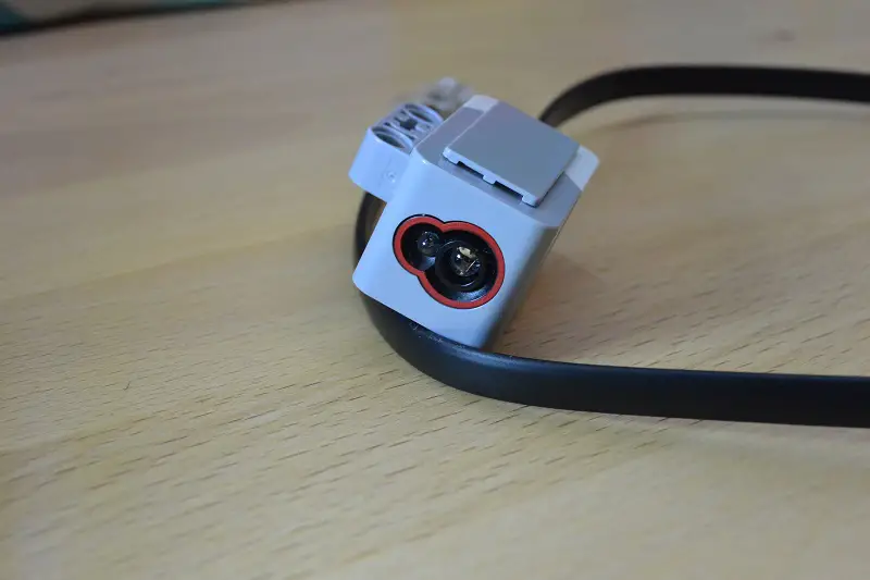
The Lego Mindstorms EV3 Color sensor can measure a
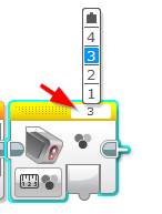
Within the EV3 Programming software, the Color Sensor block belongs to the Yellow group and it assumes that the color sensor is connected to port 3 on the EV3 Brick by default. This is not necessarily set in stone and can be changed by updating the port number on the top right of the brick:
How does the EV3 Color Sensor Work?
When looking at the
Reflected Light Intensity Mode
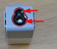
In Reflected Light Intensity mode, the EV3 Color Sensor will emit a red light from the LED lamp and measure the intensity of light reflected back into the color sensor. Using a scale from 0 (very dark) to 100 (very light), the sensor will assign a number to the intensity reading.
Ambient Light Intensity Mode
In Ambient Light Intensity mode the
Color Mode
In
EV3 Color Sensor Code Values
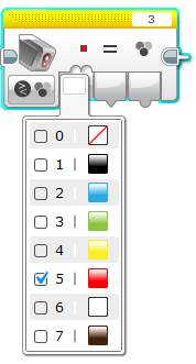
The EV3 Color Sensor assigns a numeric value to each color it recognises, the table below lists all these values (or color IDs):
| Color | Value |
|---|---|
| No Color | 0 |
| Black | 1 |
| Blue | 2 |
| Green | 3 |
| Yellow | 4 |
| Red | 5 |
| White | 6 |
| Brown | 7 |
EV3 Color Sensor Modes
There are three main modes within the color sensor programming block:
- Color Mode: Reads up to seven colors (plus it can detect the absence of color)
- Ambient Light Intensity Mode: measures the light being emitted from an external source (e.g. sunlight or a flashlight)
- Reflected Light Intensity Mode: measures the light intensity reflected off the surface of an object.
The details of how each of these modes work have been outlined within the How does the EV3 Color Sensor Work? section of this post.
Outside of these modes there are two different options you can use to run them in:
- Measure
- Compare
Each of the combination of these modes and options are outlined below:
Color Mode
Compare
In Compare Color Mode you are able to select one or more colors for the sensor to detect, once any one of the selected colors is found, the programming block will output True.
Measure
Measure Color Mode will out put the numeric value for the color that the sensor detects. This color value can then be wired into your program to activate other logic based on the output.
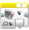
For more information on the
Reflective Light Intensity Mode
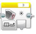
Measure
In Measure Reflective Light Intensity mode the
Compare
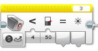
In Compare Reflective Intensity mode the EV3
Ambient Light Intensity Mode
Measure
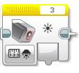
In Measure Ambient Light Intensity mode the
Compare
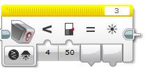
In Compare Ambient Light Intensity mode the
Can I purchase an Additional Color Sensor?
Yes, you can purchase an additional
Why would I need an additional Color Sensor?
The most common use of an additional EV3
Calibrating the EV3 Color Sensor
When running the EV3 Color sensor in Reflected Light Intensity mode then it’s recommended the sensor is calibrated, especially if lighting (or table) conditions change.
Calibrating will reteach the sensor what is black (0) and what is white (100).
How to Calibrate the Color Sensor
To calibrate the EV3 Color Sensor we’ll utilise the Calibrate Mode on the yellow Color Sensor programming block.
I’ll take you through creating this program step by step and we’ll create a program which execute the following logic:
- Reset the Color Sensor Calibration
- Show an onscreen prompt asking you to place the sensor on a black object
- Wait for the
center button on the EV3 Brick to be pressed - Calibrate the Black within the sensor and show the value on the screen for 2 seconds
- Show an onscreen prompt asking you to place the sensor on a White object
- Wait for the
center button on the EV3 Brick to be pressed - Calibrate the White within the sensor and show the value on the screen for 2 seconds
Note: if you’d prefer to download the program, I’ve put this EV3 Color calibration program together for a download in the next section.
Lets get started!
- Reset Calibration: Drag and drop a Yellow Color Sensor block up to the Start button and set its mode to Calibrate | Reflected Light Intensity | Reset
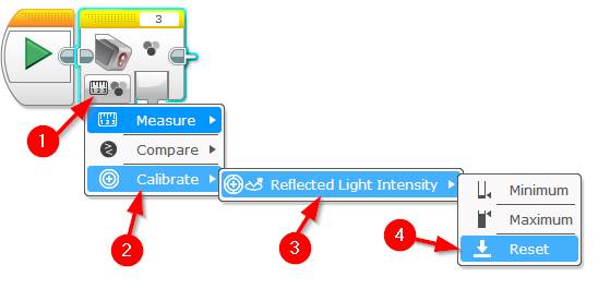
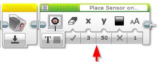
- Add a prompt to place Sensor on Black line: Drag and drop a Green Display block next to the
color sensor reset block.- Set the following attributes:
- X = 3
- Y = 50
- aA (Text size)= 1
- Set its mode to Text | Pixels and type the following text into the Text
paramiter (top right):
- Set the following attributes:
Place Sensor on Black Line
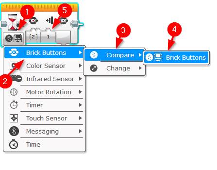
- Add Wait for the center button push: Next drag and drop
a Orange Wait block next to the display block and set its mode to Brick Buttons | Compare| Brick Buttons- Leave its brick button input set to #2 (center)
- Change the State value to 2
- Calibrate Black within the sensor: Drag an drop a Yellow Color sensor block next to the wait block.
- Set its mode to Measure | Reflected Light Intensity
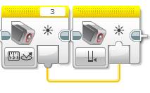
- Store the calibrated value: Drag an drop a Yellow Color sensor block next to the other color sensor block.
- Set its mode to Calibrate | Reflected Light Intensity | Minimum
- Wire the value from the Measure (the first
color sensor) into the secondcolor sensor:
- Show the calibrated value on the screen for 2 seconds: Drag and drop a green Display block after the
color sensor.- Set its mode to Text | Pixels
- Set the text field (top right) to Wired
- X = 0
- Y = 50
- aA (size) = 2
- Wire the output from the first Color Sensor block (measure mode) to the Text input on the display block:

- Add the timer for the calibration display: Drag and drop an orange Wait block next to the display.
- Set the time to 2

- Add a prompt to place Sensor on
White line: Drag and drop a Green Display block next to the wait block.- Set the following attributes:
- X = 3
- Y = 50
- aA (Text size)= 1
- Set its mode to Text | Pixels and type the following text into the Text parameter (top right):
- Set the following attributes:
Place Sensor on White Line
- Add Wait for the
center button push: Next drag and dropa Orange Wait block next to the display block and set its mode to Brick Buttons | Compare| Brick Buttons- Leave its brick button input set to #2 (
center ) - Change the State value to 2
- Leave its brick button input set to #2 (

- Calibrate White within the sensor: Drag an drop a Yellow Color sensor block next to the wait block.
- Set its mode to Measure | Reflected Light Intensity
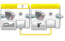
- Store the calibrated value: Drag an drop a Yellow Color sensor block next to the other
color sensor block.- Set its mode to Calibrate | Reflected Light Intensity | Maximum
- Wire the value from the Measure (the
color sensor from the previous step) into the secondcolor sensor:
- Show the calibrated White value on the screen for 2 seconds: Drag and drop a green Display block after the
color sensor.- Set its mode to Text | Pixels
- Set the text field (top right) to Wired
- X = 0
- Y = 50
- aA (size) = 2
- Wire the output from the first Color Sensor block (measure mode) to the Text input on the display block
- Add the timer for the calibration display: Drag and drop an orange Wait block next to the display.
- Set the time to 2
That’s it, you’re done! The final program should look like this:

Hit the Download and Play button and follow the prompts.
EV3 Color Sensor Calibration Program Download
If you don’t want to spend time following the instructions above, you can download a copy of EV3 Color Sensor calibration program here.
How to get Good, Reliable Readings from the EV3 Color Sensor
The
It’s also more reliable when the object it’s reading is flat.
In regards to the size of the object, as long as the object is big enough to be full contained within the light the LED lamp emits then it should be good. Anything smaller will give mixed results.
Example Color Sensor Progra m
How to: EV3 “Say Color” Program
This program does not require a build, just the EV3 Brick and the
The steps below outline the logic that the program will follow:
- Wait for the
center button to be pushed - Using the Color Sensor from within the Switch block, measure the
color value - Assess the numeric
color value and using a sound block, say the name of the detectedcolor - Loop back to step one
Let’s get started:
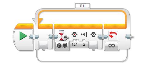
- Place an orange Loop block to the right of the Start block
- Leave its loop condition as infinite.
- Place an orange Wait block inside the Loop block
- Change the mode to Brick Buttons | Compare | Brick Buttons
- Brick Button ID(s) = 2
- State Input = 2
- Drag and drop an orange Switch block next to the Wait block.
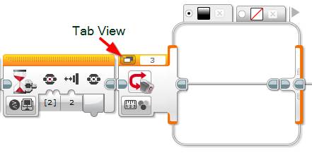
- Set its mode to Color Sensor | Measure | Color
- When dealing with a few cases within the switch I find it easiest to switch it to Tab view (top left of the block).
- Click the rightmost plus button on the Switch block to add a new tab, click the red question mark on the new tab and select Blue.
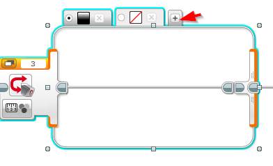

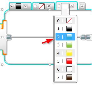
- Continue the process above until a tab exists for each
color (up to brown – 7). once that’s complete, you should now have 8 tabs:

- Now it’s time to add the speech to the program. Select the Black color tab and drag and drop a green Sound block into it. Select the Black color sound file by clicking the top right of the block and selecting Lego Sound Files | Colors | Black

- Repeat step 6 for each color
- For the “No Color” tab we want it to play the words “No Color”: drag and drop 2 green Sound blocks. Set the first to play file: Lego Sound Files |Communication | No and the second Sound block to play file: Lego Sound Files |Information | Color.
- Click Download and Play to test out the program.
If you would like to try out another
Feel free to leave a comment if you have any questions.

Comments
Hello Glenn,
Your color sensor article is really helpful for our team. We are using 2 sensors to follow a black line. We wonder if it matters when we place the sensors in the direction where the central axis of 2 lenses of a sensor is parallel to the line or we put the sensors in the direction where the central axis of 2 lenses is perpendicular to the line we trace.
We appreciate any of your help.
Jane
Hi Jane,
Thanks for submitting the comment – I prefer to put the sensors parallel to the line.
Here’s a great YouTube clip on this: https://youtu.be/3UzyynQh9F8
Cheers,
Glenn
Hi,
Thanks for this information. We are working on a line follower which take turns when it sees colour green. Our line follower program uses light intensity mode and the turn left or right part uses colour mode of the sensor. We are wondering if we can (without error) switch between two modes of the colour sensor in the same program. Though we have tried it and most of the times it works however sometimes it fails. When it fails the robot starts spinning round and round when it is supposed to turn left or right when the sensor sees green by being in colour mode.
Hi,
I haven’t personally come across this before. However one thing you may want to check is your firmware, I have heard that rolling back to an earlier firmware version may help with this.
Cheers,
Glenn